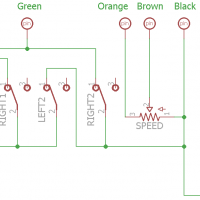
Hey all, I know this is an ancient post but i thought i’d drop a bit of info off for you all. I’m in the middle of rebuilding my own foot switch and i took apart my dad’s foot pedal to trace the schematic in Cad Software to figure out the wiring. I’ll post photos of what i really mean but here’s what i’ve got!
The Pedal consists of 7 electrical connections i’ve labeled on the schematic by color. In order to build a replacement with more traditional parts(That wont suck and use these cheap PCB mounted switches) you’ll need 2 DPDT Momentary foot switches for left/Right controls, 1 SPST Momentary foot switch for you’re ON control, 1 SPST latching foot switch for the Always On Control and a Simple Potentiometer knob for the dial 1K Ohm Logarithmic. It all looks really straightforward. I’m excited to give it a go. But here’s the schematic. I’ll update with more Photos and info once i’ve got it.
